This article is about baking normals with the Cycles Render Engine. But it also contains excerpts from our book The Cycles Encyclopedia. This is where you can get extensive information about how normals work internally and what they are used for.
A few pointers that were not covered in the tutorial:
- If you want to know where to use normal maps, please visit the Blender Internal version of baking normals tutorial.
- If you use a texture to influence the displacement of the material of the object you bake from, they will be taken into account by the baking.
- There is a swizzle option you can use to flip axes. If you are going solely for Blender and Cycles there is no need to use these options, as for openGL, but NVidias Direct X uses the Y channel as up so you need to exchange Y for Z.
Cycles Encyclopedia Excerpt: The Truth About Normals
Normals are something you come across everywhere in computer graphics. Normals are used in shading, but also for particle systems, smoke simulations, texture inputs and so on.
But what are normals? Consider the following: A ray of light hits a surface. Can you determine the angle between the ray and the surface? Try it for yourself by holding a pencil touching a piece of paper. There are several possible angles you could measure (fig. 15.1, left). In CG, we want to be certain about the angle, so there should only be one. That is where the normals come into play. If you raise the end of your pencil so that it is pointing exactly upwards, there is only one angle to measure, all around the pen, and that is 90° or a right angle. The normal of a face is simply a vector perpendicular to it. Now calculating the angle of the ray becomes really easy, since you can calculate the angle between two lines without ambiguity. When a light ray hits a surface, its direction is computed from the face normal at that point.
A normal also has a second function. By looking at the normal you can determine whether you are looking at the front or the back of a face, because the normal will always point away from the front side.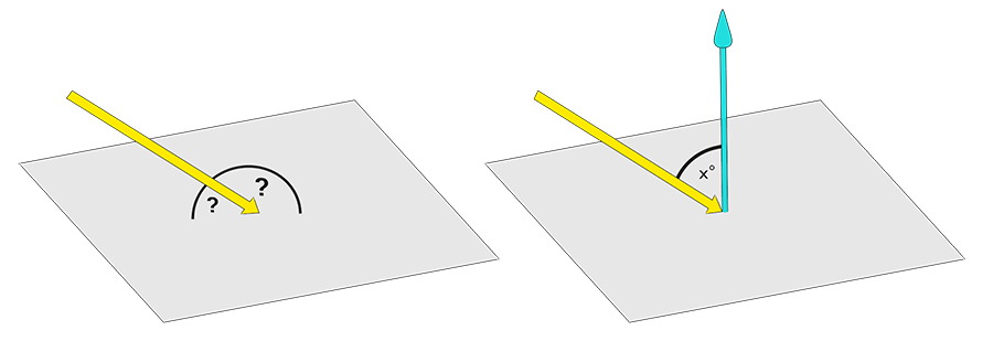
Fig. 15.1) left: It is not possible to tell at what angle an incident ray hits a plane directly. However, you can calculate the angle between two lines. Since a normal is orthogonal to all directions of a face, Blender can draw all vital information about angles from the normals of a face (right).
The cool thing about normals is that you can manipulate them and thus you can change how the renderer perceives the angle of incident rays. That concept is used in smooth shading. Even if a surface has very steep angles, it can be forced to appear smooth by interpolating the normals between vertices. Consider the following example:
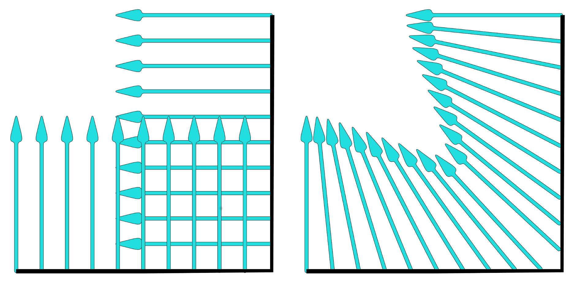 Fig. 15.2) On the left the normals of a corner of an object when shading is set to flat. On the right the same object with smooth shading. The direction of the normals gets interpolated for each shading point.
So by interpolating the normals an angular surface can look rounded. In Cycles, the effect applies not just to the look of a surface but also on the way light is traveling, ie. how it reflects and refracts:
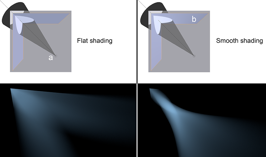
Fig. 15.3) The effect of smooth shading on reflections. On the top the setup - a spot lamp (a), diffuse ground and a model of a corner made from two faces with a glossy shader set to sharp (b). On the left with flat shading for the corner object, on the right with smooth shading. On the bottom left the corner was set to flat shading. The light was reflected as expected from a mirror. On the bottom right the corner’s shading was set to smooth. You can see that the outline, where the light hit the corner was sharp, but the reflection behaves as if it was produced by a concave mirror.
Not just faces have normals but also vertices. For vertices the direction of the normal is determined by the adjacent faces. You can visualize them directly in Blender by going into edit mode, then to the properties panel (N-Menu) where you will find symbols to visualize the normals in the Mesh Display section:

Fig. 15.4) Vertex normals (blue) and face normals (turquoise) visualized in the Blender viewport by clicking on the corresponding symbols under Normals.
Normal Maps
As you can see, the direction of a normal is not carved in stone. Interpolation due to smooth shading is one example where the normals of a surface get changed. But you can also influence the local direction of a normal directly, using a texture or so-called normal map. The three color channels of the texture will influence the three vector components of the normal (Red: X, Green: Y, Blue: Z).
Let’s have a look at the math behind normals. As you can see in fig 15.1, the angle in which a ray hits a surface is determined by the angle of the normal at the exact spot the ray “arrived”, called a shading point. Faces - in theory - have an infinite amount of normals, but each shading point has only one. So let’s look at that single normal. The angle at which the ray hits a surface is calculated by the angle between the direction of the ray and the normal. This and the material settings influence the behavior of the ray after the collision. The easiest example is a perfectly glossy surface, because there is no coincidence factoring in on the behavior of the rays. If it hits a plain surface, its angle of incidence equals the angle of reflection. If you plug the normal output of a geometry node into the color of an emission shader, you can see the normals expressed as colors. Red stands for X, green for Y. If you use a normal map node in your material, the angle of individual shading points can be altered, using the color channels as vectors (fig. 15.6). So the surface is pretending to point in a different direction than the geometry declares. To determine how much and in which direction the true normal is altered, Cycles looks at the color information. Since there is nothing actually sticking out of the surface, it will only work from fairly flat angles (fig. 15.5), but in those cases it actually works pretty well.
The effect of a normal map is more convincing from steep angles, as for shallow angles the lack of geometry becomes evident:
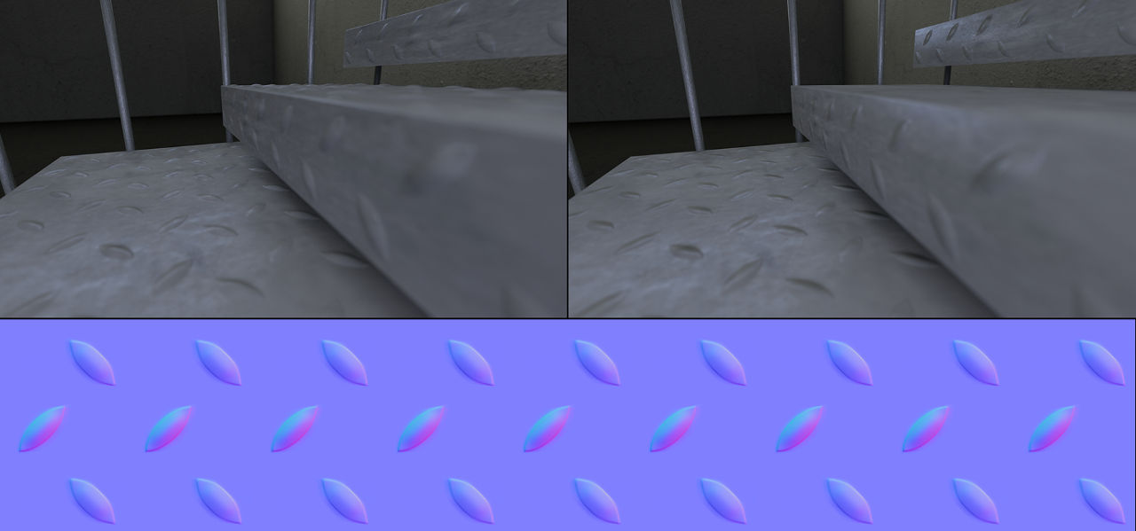
Fig. 15.5) Bottom: An example of a normal map. Top left: A scene with stairs where the bumps were modeled, it contains 270.000 polygons. Top right: The same scene using a normal map, only 930 faces. For very flat angles, the missing geometry becomes evident.
The normal map (bottom) was created by placing simple planes under each surface of the stairs and baking the high resolution geometry as a normal map onto them.
The mostly blueish colors you see in fig 15.5 make up a tangent space normal map, where a value of 0.5 for red (X) and green (Y) is considered straight up and a blue usually has a value of 1.0 as it is only needed for normalization purposes. At a pixel with red, values smaller than 0.5 the normal direction will be shifted to the left, values higher than 0.5 make it point to the right:

Fig. 15.6) Array of pixels that represent normals, just the red channel. Values smaller than 0.5 make the vector point to the left, values higher than 0.5 make it point to the right and exactly 0.5 is straight up.
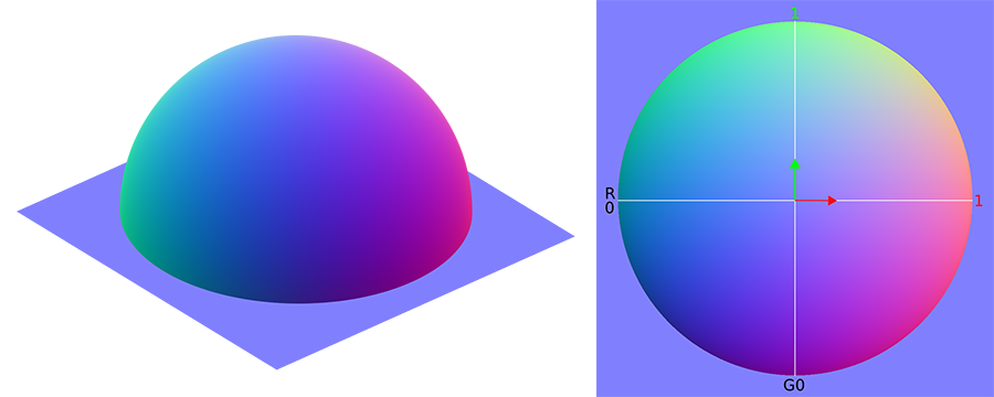
Fig. 15.7) Normal map baked from a hemisphere. On the left the original model with real geometry. The colors represent the direction of the real normals. On the right the baked normal map. The red and green channels form gradients from left to right (red) and bottom-up (green).
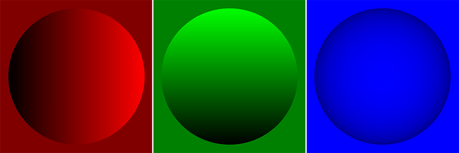
Fig. 15.8) The normal map from fig.15.7 split into red, green and blue channel.
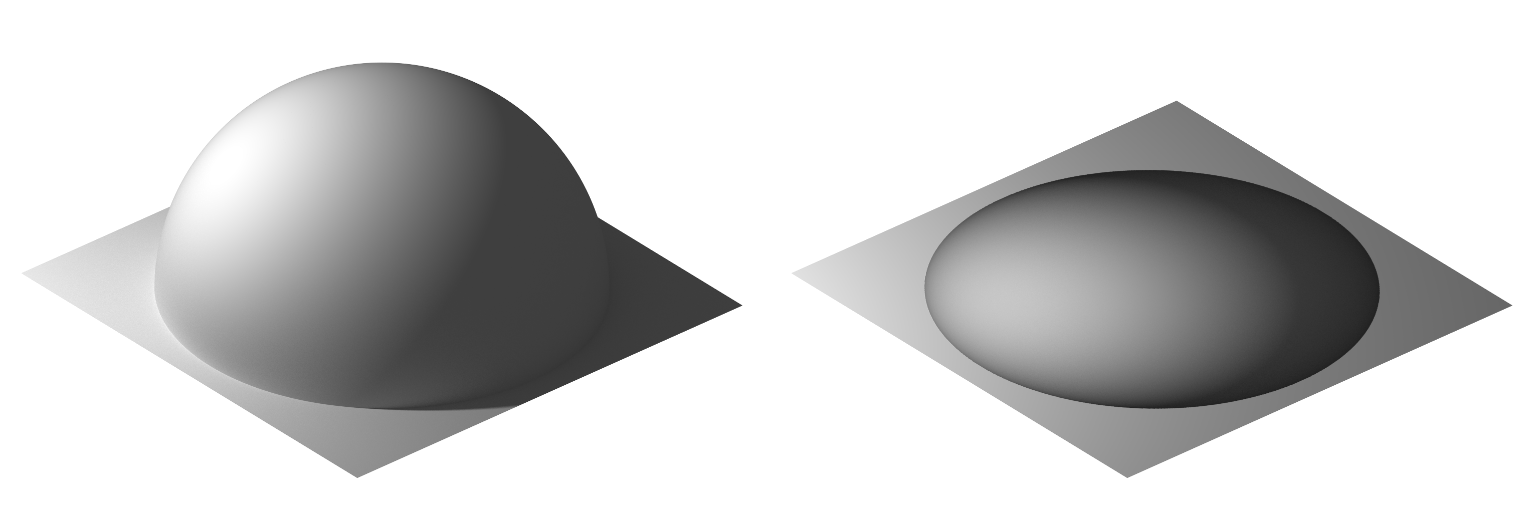
Fig 15.9) Left: the geometry from fig. 15.7 with a point lamp shining from the left. Right: a plane with a normal map baked from that geometry and the same light setup. Although the light rays were reflected into the correct directions, the silhouette of the sphere is not rendered. Therefore it is not able to cast shadows onto the surface or interact with bouncing light.
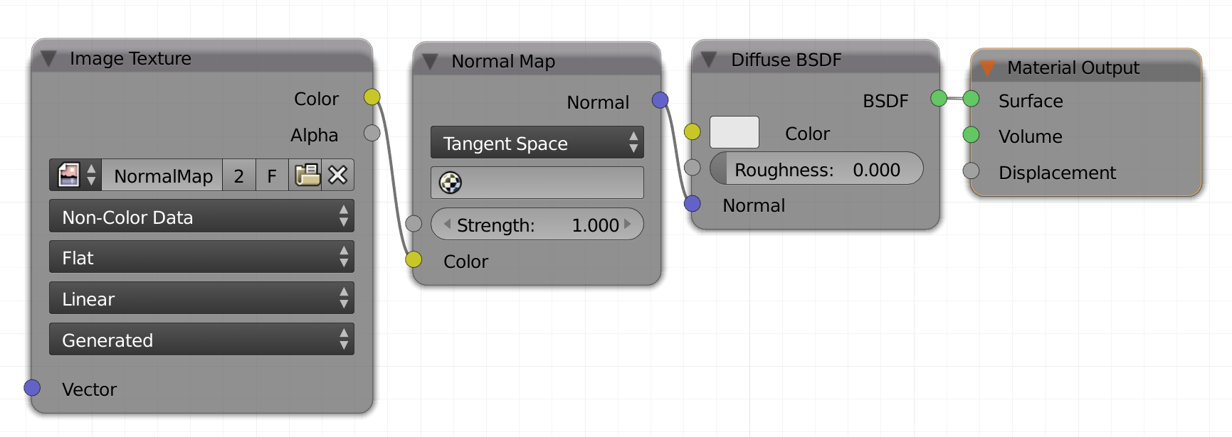
Fig. 15.10) The node setup for using normal maps in Cycles.
You can pretend to change the direction of the normals of any shading point by adding vector information through a color map. The proper way to do so in Cycles is to load the normal map into an image texture node, set this to non-color data. Also insert a vector -> Normal Map node. Then connect the color out of the image to the color in of the normal map node. The outgoing normal vector needs to be plugged into the normal input of your shader node (see fig. 15.10).
This article is an excerpt from the BlenderDiplom eBook
